A pre-processing GUI for our APIs
Import meshes: nodal coordinates and element connectivity
Create group of nodes by picking individual nodes or by defining a picking area
Create group of elements by picking individual elements or by defining a picking area
Define materials
Define properties, including element types, thickness, and associate materials
Assign group of elements to the property
Define boundary conditions
Define loads
Picking capabilities for nodes and elements
Manipulation of mesh models, trackball 3D rotation
Open and save of API files
Work is continuously being done on the GUI to extend it with more advanced capabilities. Our existing customers will have automatic updates for the GUI.
We can tailor the GUI for Customer's needs, please contact us.
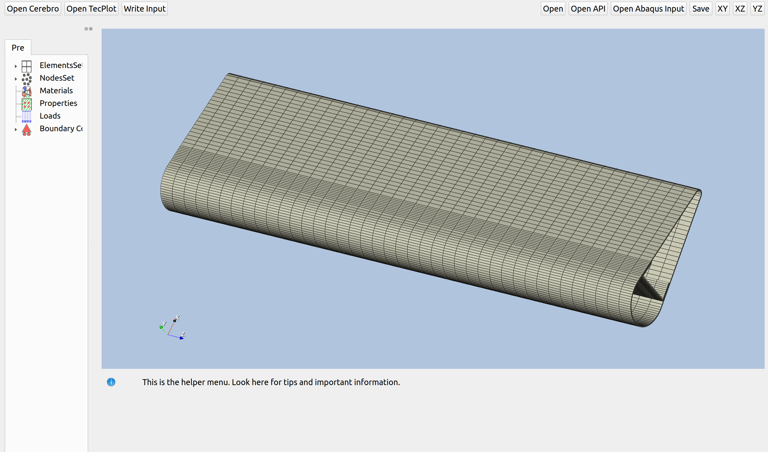

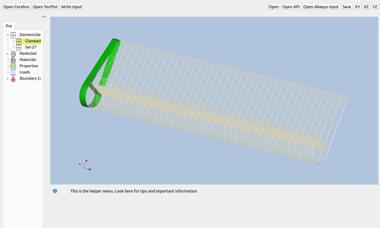

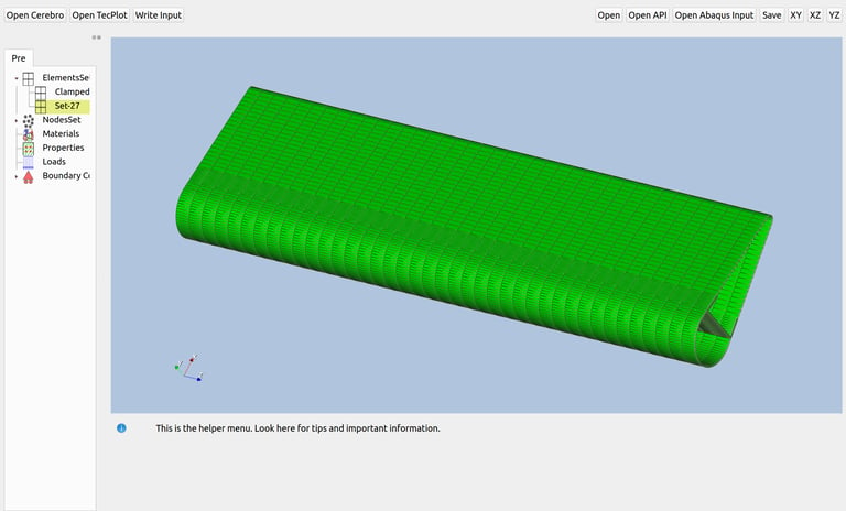

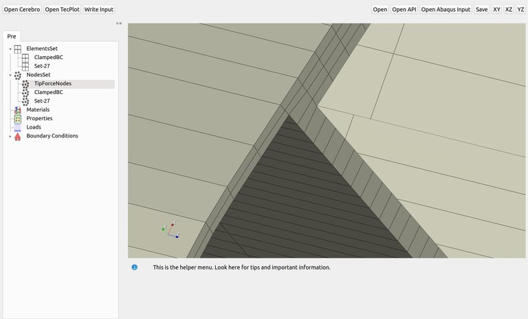

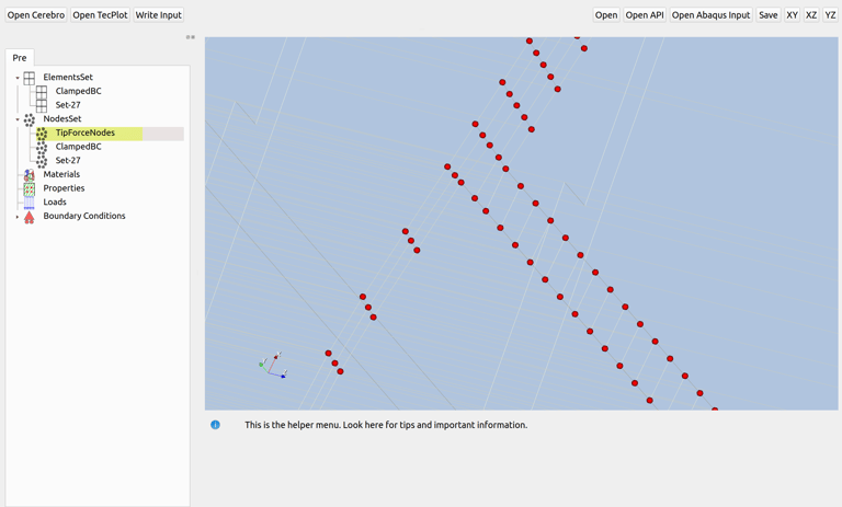

The pre-processing GUI has a toolbar with open/save capabilities, a render window where the construction of the model takes place, a help window at the bottom, and a Tree menu at the left for defining the inputs for the mesh model.
The pre-processing GUI does not allow CAD operations, it operates on an imported mesh model.
At the moment, Abaqus input files can be imported and the APIs input files can also be open with their own format. We will adapt the GUI to import any other mesh file formats (nodal coordinates and element connectivity) if requested by the customer.
The "ElementsSet" widget allows the creation and modification of group of elements. It uses element picking (individual or area picking) and it can also import element sets from Abaqus input files.
The element sets can be visualised in the render windows by double-clicking on the Tree for the name of the set or by right-clicking -> show/hide options on the drop-down menu window.
Elements can be added or removed from existing element sets.
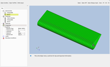
When an element set is double-clicked its name on the Tree becomes highlighted in yellow alongside with the elements in the set shown in green colour in the render window.
The "NodesSet" widget allows the creation and modification of group of Nodes. It uses nodes picking (individual or area picking) and it can also import node sets from Abaqus input files.
The node sets can be visualised in the render windows by double-clicking on the Tree for the name of the set or by right-clicking -> show/hide options on the drop-down menu window.
Nodes can be added or removed from existing node sets.
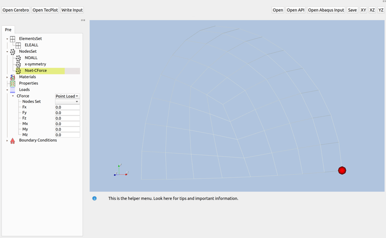
When a node set is double-clicked its name on the Tree becomes highlighted in yellow alongside with the nodes in the set shown in red spheres in the render window.





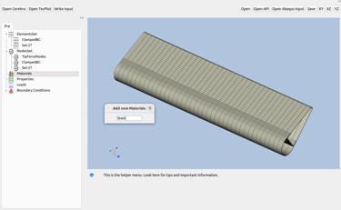
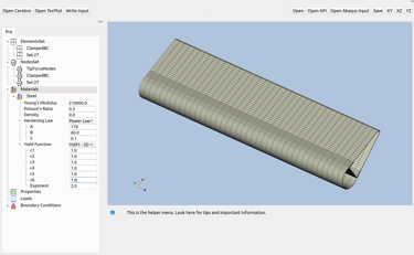
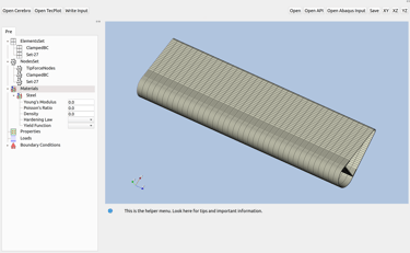


The "Materials" widget on the Tree allows the creation and modification of materials.
To create a new material we have to right-click on the materials widget. A new pop-up window will appear and a name for the new material must be given.
The new material will now appear on the Tree and it could be expanded for the input of material properties.
If another material is required, then the "Materials" widget must be right-clicked again and a new material name must be input. The process repeats for the new materials.
Click on the image gallery for more detailed inspection of the GUI for the definition of materials.
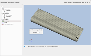
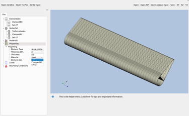
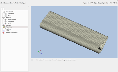
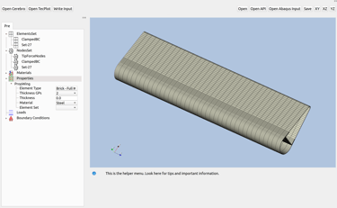
The "Properties" widget in the Tree allows users to create and modify element properties, specifying details such as element type, numerical integration rules, thickness (for shell elements), and the material (as defined in the "Materials" widget).
To create a new property, right-click on the Properties widget. This action opens a pop-up window where a name for the new property is required. Once named, the new property will appear in the Tree, ready for expanding and configuring with element-specific settings.
If additional properties are needed, right-clicking the Properties widget again and entering a unique name will repeat the process.
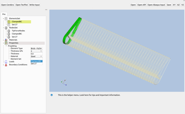
To assign elements to properties (and their respective materials), select the Element Set in the combo box. As you hover over element set entries in the combo box, the associated mesh highlights in green in the render window, providing a clear view of the elements linked to each property. If elements aren't included in any current element set, create a new set, which will automatically appear in the Element Set combo box in the Properties widget.
Refer to the image gallery for a closer look at the GUI layout and property definition steps.
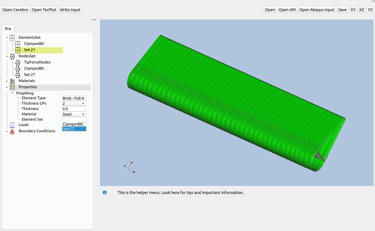


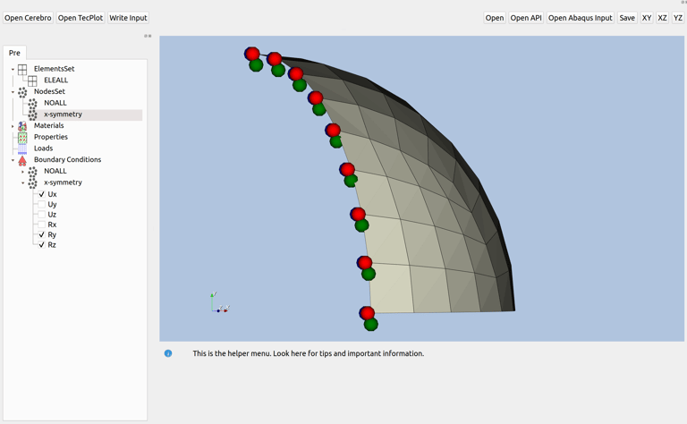
The "Boundary Conditions" widget in the Tree allows users to define boundary conditions (BCs) for the model, assigning them to specific Node Sets. Node Sets are automatically added to the BCs widget in the Tree, where all defined Node Sets are listed. However, this does not imply that each Node Set has a BC assigned. Only when the checkbox for a Node Set under the BC widget is selected will BCs be applied to all nodes within that set.
A colour code visually represents constrained degrees of freedom in the render window: red spheres indicate constraints in the x-direction, green in the y-direction, and blue in the z-direction.
For more details on the GUI layout and BC definition steps, refer to the image gallery.
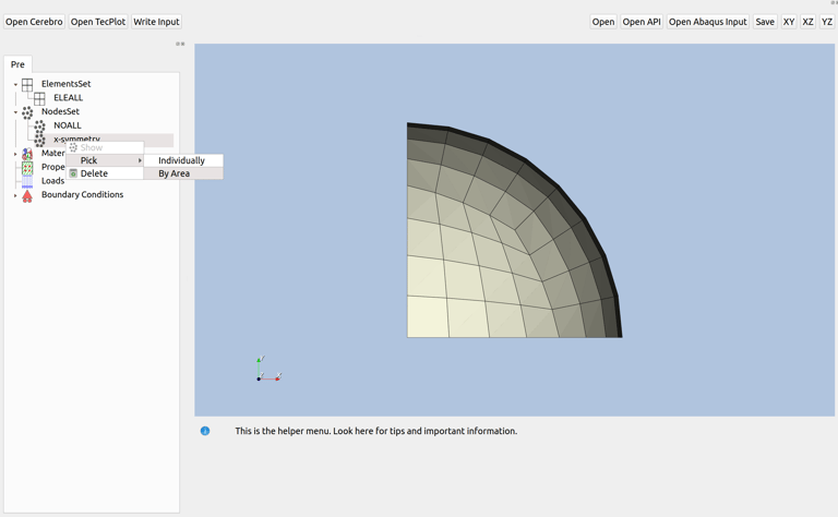
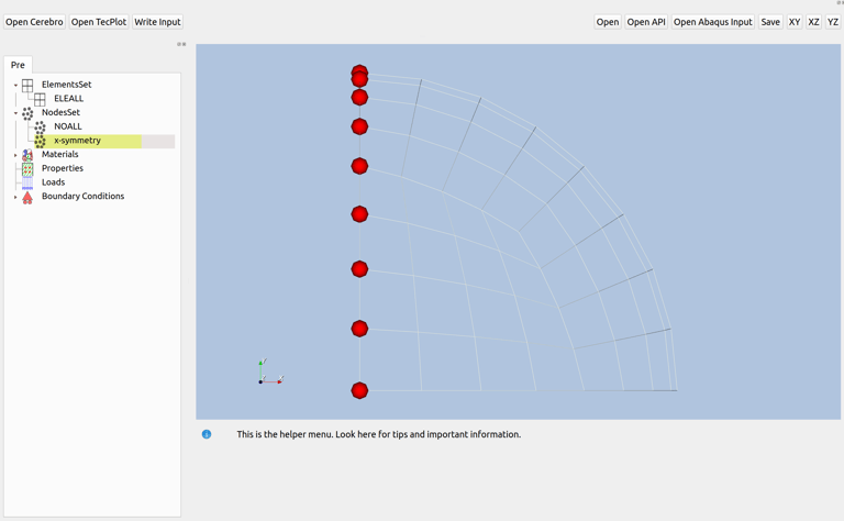
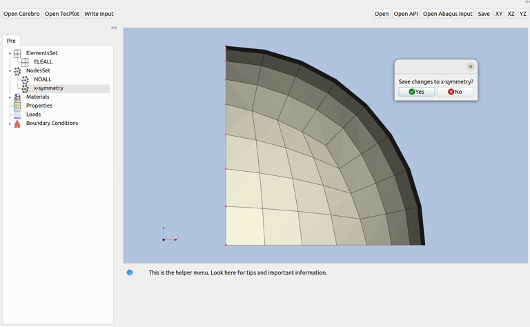


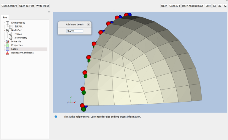
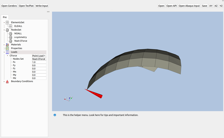
The "Loads" widget in the Tree enables users to define loads for the model, assigning them to specific Node Sets or Element Sets. These sets are available in a combo box within the load settings. New loads can be created by right-clicking on the "Loads" widget in the Tree and assigning a name, which adds the new load under the "Loads" widget. Users can currently select between two load types: Point Loads and Pressure, defined in the load type combo box. A second combo box allows selection of a Node Set (for point loads) or an Element Set (for pressure loads), applying the load parameters to all nodes or elements in the chosen set.
A colour code visually represents loads in the render window: red arrows for x-direction loads, green for y-direction, and blue for z-direction loads.
For further details on the GUI layout and load definition steps, see the image gallery.




A post-processing GUI for our APIs
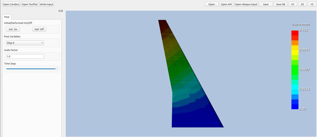

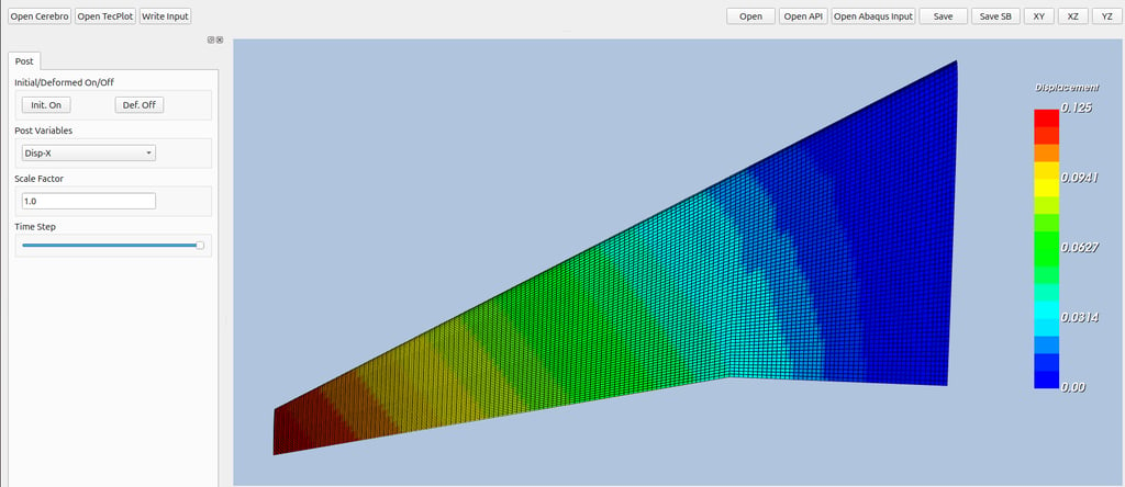

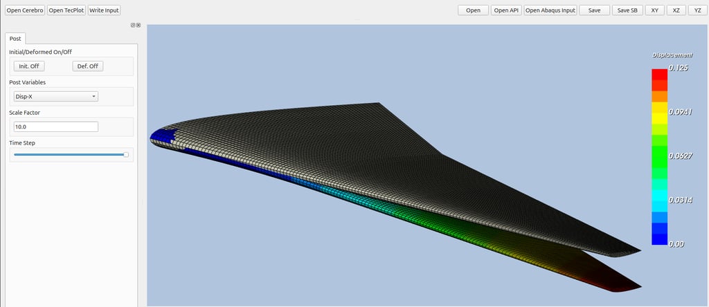

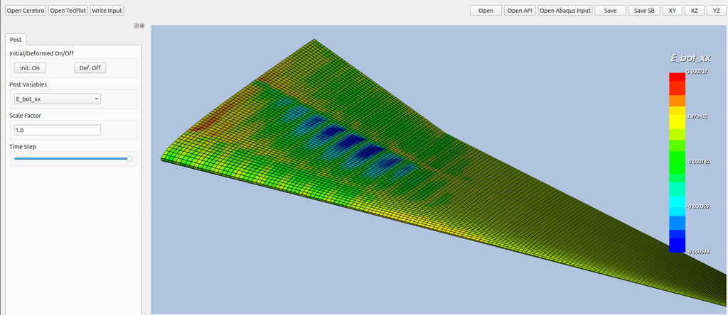

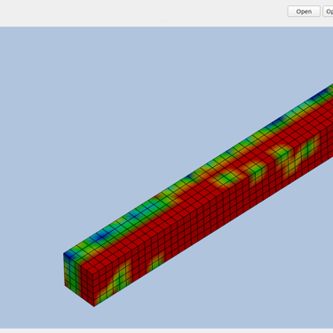
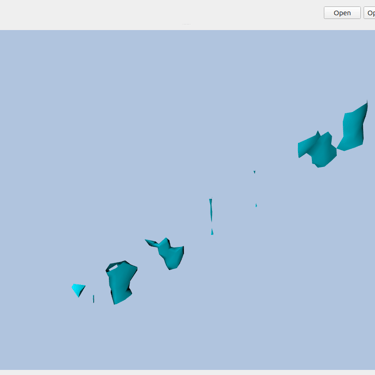
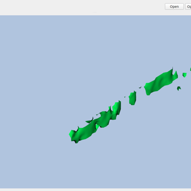
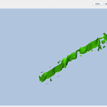
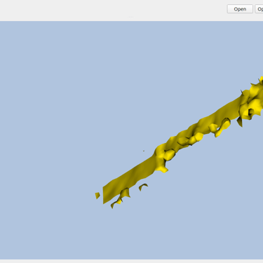
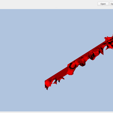
Unlock deeper insights with dynamic iso-surface visualization, allowing you to explore multiple contour levels inside 3D elements — fully integrated with our advanced Hexa8 and MRESS APIs.
One license FREE with a Business API subscription
Terms & Conditions for Industry Software License




Fill the form for subscribing this API.
We will not be able to license the GUI if the Terms & Conditions are not accepted upon submission of this form.
Get in touch
Technical Support: support@mechinmotion.com
Sales: sales@mechinmotion.com
